简介:通常,电潜泵处理气体方面都比较困难。不考虑含气液流的本身性质的影响,而一旦有气体进入电潜泵,就会发生一些问题。经验表明,选择一款能够应付气体的电潜泵不是一件简单的事。
Severe pump cycling results in wells that experience high gas volume fractions, especially those with varying flow regimes.
In general, electric submersible pumps (ESPs) do not like gas. Regardless of the source or nature of gas inclusions in the flowstream, problems can occur when the gas reaches the ESP. Recent experience has revealed that selecting the most appropriate gas handling solution is not a simple task. The reason is that gas inclusions can manifest themselves in many ways from massive slugs to entrained bubbles at a broad spectrum of flow rates and pressures. Different well geometries and completion styles can affect the way gas flows or agglomerates in the flowstream. Accordingly, each situation must be evaluated on its own merit.
Because the gas flow regime can be variable, real-time monitoring of flow, pressure, and temperatures provides valuable information in deciding the best method of gas handling, but it also has significant long-term benefits in detecting changes in the operation that could lead to premature pump failure.
ESPs’ low tolerance for gas is usually no more than 10% to 20% gas volume fraction (GVF). Because ESPs rely on centrifugal force to move fluid, generally radial or a combination of radial and axial, high- and low-pressure areas are created in the pump stage vanes as they rotate. As gas enters the pump, the lighter gas phase slips apart from the heavier fluid phase and accumulates on the low-pressure side of the blade until it finally blocks the passage of the entire vane/ vanes in the pump stage (Figure 1).
As gas enters the intake stage of an ESP, it eventually causes the pump to gas lock. Surface equipment used while producing the well can help alleviate this problem. In the case of a switchboard application?fixed speed?the options are limited. In a variable speed drive (VSD), the speed of the pump can be changed as the pump load varies due to gas slugging, allowing the pump to ride through the slug.
In a case discussed here, the VSD was set up in current mode where the drive followed a preset current point to track the operation of the pump in lieu of shutting the system down. The use of a VSD has its limitations. If the GVF is high enough, it eventually leads to a gas locking condition. When this happens, the flow of liquid stops, and the result is a sharp increase in motor winding temperature and a sharp decrease in load on the motor. If the temperature spike is not detected and steps are not taken to remediate it immediately, the ESP can be destroyed. If the flow regime includes gas slugging, the damage can be even more precipitous (Figure 2).
Dealing with gas
Over the years, operators and service partners have developed methods to deal with gas in pumping wells.
In some cases, the system can be equipped with a shroud that displaces the pump assembly intake point down below the source of gas influx (usually the perforations).
Free gas entering the well experiences simple gravity separation and bubbles up into the annulus, allowing the liquid phase to enter into the shroud and flow up to the ESP intake. This technique is called gas avoidance, as the shroud minimizes the amount of gas reaching the pump’s intake altogether. In deviated wells, gas entry can be avoided by using a weighted self-orienting intake that always draws from the low side of the casing, thus avoiding gas flow that is percolating up the high side due to gravity separation (Figure 3).
In some cases, gas can be separated in advance of the pump intake either by forcing production to take a tortuous path to the intake ports or by creating a vortex in the flowstream. For higher GVFs, various rotary techniques can be employed. These add energy to the flowstream to stimulate the separation process. Centrifugal separators assist in separating the gas from the liquid and disperse the gas through discharge ports into the casing to be produced up the annulus.
Advanced gas handlers (AGH) operate on the principle of homogenizing the produced mixture as it passes through the pump, allowing for increased GVF to be handled in a way that surpasses the effectiveness of the centrifugal separator.
The AGH homogenizes the gas and liquid phases, compresses a portion of the gas back into solution, and induces a gas lift effect in the tubing above the pump. This enables the pump to produce the mixture with a limit of approximately 45% GVF without gas locking, reducing the load on the pump and improving its overall lifting efficiency.
The most effective technique in terms of gas handling employs axial flow technology, which has the capacity to effectively handle GVFs up to 75%. Developed jointly by Institut Français du Pétrole, Total, and Statoil, the Poseidon gas handling system is a multiphase helicoaxial pump that fits between the ESP intake ports and the ESP itself (Figure 3).
The system is designed for ultra-high GVF oil wells or high-rate gas wells that require dewatering and are produced by ESPs. It has been characterized as a multi- phase gas handler because it can deal with a very broad spectrum of gas flow regimes. It can be installed above a gas separator so separated gas can be vented to the casing annulus, or directly between the pump intake and the pump.
The device adds axial velocity to the fluid to the point at which the centrifugal pump can handle it. It essentially charges the first three impellers of the ESP so the gas does not accumulate in the vanes and block the passage. Once charged, the pump can efficiently move the resulting liquid/gas mixture without losing its prime. Even if a large slug of gas appears, the pump can usually handle it.
Experience has shown that companies faced with gassy wells should follow best practices when selecting and implementing gas handling technology. Users recommend that downhole monitoring of pump performance should be employed on all ESPs used in high GVF wells. It is possible to monitor multiple sets of parameters simultaneously using sensors in the pump and motor, transmitting the resulting data uphole multiplexed on the power cable. One set of sensors measures pump/motor parameters such as intake and discharge pressure, motor winding temperature, vibration, and current leakage.
The VSD measurements such as current, motorspeed, and frequency are measured and combined on the same set of data for monitoring and trending. Pump performance can be fine-tuned using the combination of realtime data monitoring and the use of a VSD at the surface. The VSD provides the capability to control and manage the ESP during all phases including startup and initial production. Flow rate, dynamic head, and drawdown can be optimized and, in many cases, gas slugging effects can be limited.
One problem with automated systems is frequent shutdowns and automatic re-starts. Each time an ESP re-starts, its life expectancy is reduced. Accordingly, it is most desirable to tune the pump so it operates continually, with re-starts eliminated or at least minimized.
A case in point
Chesapeake Energy faced several gas-related challenges in one of its US onshore fields.
The field includes 26 horizontal producing wells with liquid production rates varying from 100 b/d to 2000 b/d. Gas/liquid ratios (GLR) varied as well from as little as 150 scf/stb to 15,000 scf/stb. Clearly, a one-size-fits-all solution was inappropriate?each well had to be evaluated individually and the optimum solution identified. Wells experienced frequent gas-locking, resulting in lost revenue and production interruptions. Shutdowns were also experienced because of power outages or surges resulting in field failures. In addition, startup was difficult, and getting the well stabilized was even more of a challenge.
The implications of these various problems included short pump run life of between 10 and 30 days, unstable production rates and volumes, considerable lost revenue due to downtime, and increased field labor by operations and maintenance personnel. Looking at the reservoir as a whole, it was reckoned that the collective problems resulted in a reduced field recovery factor.
The axial flow gas-handling system was installed on many wells in the field with high GLRs with improved results over the AGH technology. In addition to improved consistency in production on almost all wells where it was installed, several wells that simply could not be pumped with AGH technology were able to be produced with the axial flow system. This technology increased the window where ESPs are effective in this gassy oil reservoir.
A collaborative effort was launched with the objective of ensuring consistent production from all wells at maximum allowable drawdown. The most difficult wells were given special attention, and each well was addressed individually so solutions could be customized.
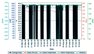
Real-time monitoring was a key factor in developing the right solution for each well. Until the time when Chesapeake installed its own automation system, monitoring was facilitated by the Schlumberger ESP Watcher surveillance and control system for ESPs, providing 24/7 monitoring to maximize uptime (Figure 4).
Ultimately, it was decided that the conventional wisdom of protecting a pump with current would not work due to the erratic flow characteristics of a high GVF well, so the ESP was protected by monitoring motor winding temperature. The system ties the downhole motor temperature measurement directly to the motor controller. This enables the ESP to ride through gas slugs without shutting down due to unstable flow rates and still protects the system.
A key benefit of the system was that both Chesapeake and Schlumberger could review the data and trends simultaneously through the Web-hosted system and make informed decisions on how to adjust the pump controls or settings without causing damage to the ESP.
Each well was considered separately and tuned for consistent performance with very little cycling. Secondarily, by analyzing the production and pump performance data for each well, drawdowns could be optimized.
The field telemetry system gathered and transmitted all relevant data to Chesapeake’s production management team, and most fine-tuning could be performed remotely without the necessity of a field visit. Pump speed could be varied, back pressure could be tuned, and drawdown adjusted.
It has been proven that with the implementation of the gas handling system, the ESP being controlled and monitored remotely, and improved collaboration between operator and service company, there has been a significant reduction in restarts. At the very least, by monitoring pump parameters in real time, Chesapeake found that it can anticipate some field failures before they occur and take steps to minimize downtime and the collateral damage of a major pump failure.
 发布信息
发布信息
